Gate, Globe and Check Valve

Petrosadid: Gate, Globe and Check  Valve

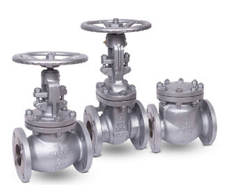
• A Globe valves is a linear motion valve and are primarily designed to stop, start and regulate flow. The disk of a Globe valve can be totally removed from the flowpath or it can completely close the flowpath.

• Gate valves are primarily designed to start or stop flow, and when a straight-line flow of fluid and minimum flow restriction are needed. In service, these valves generally are either fully open or fully closed.

• Check valves are "automatic" valves that open with forward flow and close with reverse flow. The pressure of the fluid passing through a system opens the valve, while any reversal of flow will close the valve. Exact operation will vary depending on the type of Check valve mechanism.

For more information please contact our
Customer Support Center:
Customer Support Center
image
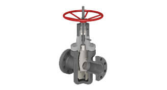
Gate Expanding Trough Conduit

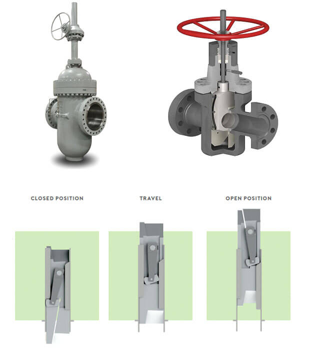
This type of valve includes in itself the features of a through conduit service and of a standard gate valve with a parallel seating surfaces. The through conduit service implies the continuity of fluid flow conduit, excluding any dirt accumulation in the body cavity. The gate is in two halves (the so called “gate” and “segment”) with angled sliding surfaces, kept together by springs or by a lever system for larger dimensions.

Construction is available with single expanding or double expanding system. In the first case, the two halves of the gate are pushed against the seats in the valve closed position by having an internal stop acting on one of the two halves. In the second case the same expansion is also obtained in the valve open position.

During the gate travel from open to close, or close to open, the gate springs or the lever system prevent the gate from being in contact with the seats by “contracting” the two gate halves together. Usual construction is bolted bonnet. Petrosadid can supply these valves in a variety of materials: carbon steel, low temperature carbon steel, austenitic stainless steel, duplex and super duplex stainless steel and nickel alloys.

Seating surfaces (seats, gate, sliding surfaces of the two gate halves) are provided with tungsten carbide coating, particularly for high pressure services.

image
image
Swing Check Valves

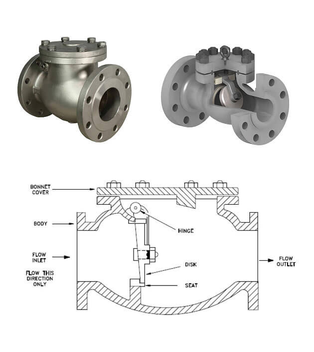
Swing check valves are best fit for horizontal pipeline installation. Special cases can be evaluated and developed upon request. For small valve sizes, a vertical installation (only with upward flow) is still possible, but for heavier weights of discs chattering issues can occur. Dampers or counterweight shall be then provided.

COVER

The cover is in carbon or stainless steel and is also available in many other Corrosion Resistance Alloys. The connection sealing surfaces are raised face or ring joint to suit the valve rating.

BODY

The body is in carbon or stainless steel and is also available in many other CRA. It is carefully designed for total reliability, to keep the pressure drops to a minimum and simple maintenance. The basic dimensions, wall thickness, face to face and flanges, comply with the relevant BS, API and ASME standards. The body-to-cover flange is circular. The sealing surface for connection to the cover is recessed in the 150 and 300 Class and ring joint for higher ratings. The body is threaded for a renewable seat and an integral over-travel stop for the disc is incorporated. Two threaded bosses are provided for the location of the hinge pin. Bosses are eventually provided for drain threaded connection.

COVER BOLTING

Bonnet studs and nuts are manufactured from alloy steel to the relevant ASTM standard.

HINGE PIN

The hinge pin is part of the trim, in forged stainless steel and is machined from ground bar. The hinge pin is locked in the body with two threaded NPT plugs. The pin can be removed for maintenance of the valve.

SEAT RING

Welded-in-seat ring are supplied as a standard. The rings are part of the trim of the valve. For threaded solution, the outer diameter is threaded and its bore is notched for easy installation and dismantling. Special attention is given to the seating face which is ground and lapped, for a perfectly tight seal.

DISC

The disc is part of the trim and is in forged or cast steel. On the back face there is a threaded spigot for the connection to the hinge arm by a nut and cotter pin. The seating surface is ground and lapped.

HINGE

The hinge is made by forged steel and in cast steel.

image
image
Lift Check Valves

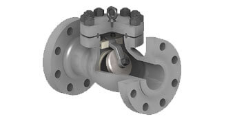
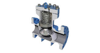
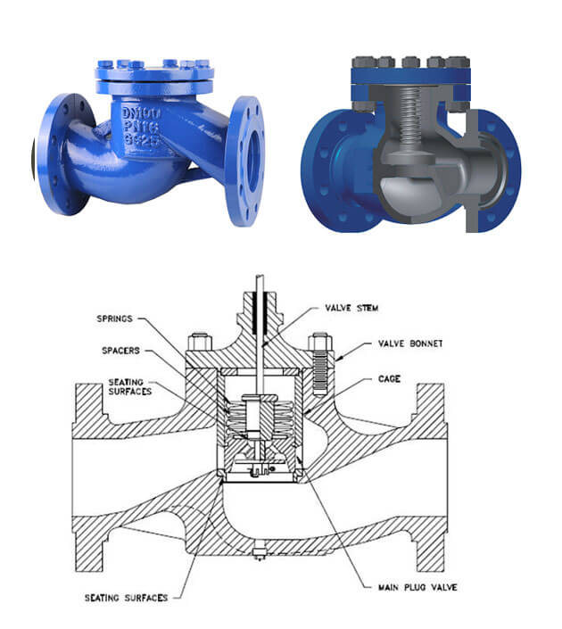
The seat design of a Lift-Check valve is similar to a Globe valve. The disc is usually in the form of a piston or a ball.

Lift Check valves are particularly suitable for high-pressure service where velocity of flow is high. In lift Check valves, the disc is precisely guided and fits perfectly into the dashpot. Lift Check valves are suitable for installation in horizontal or vertical pipe-lines with upward flow.

Flow to lift Check valves must always enter below the seat. As the flow enters, the piston or ball is raised within guides from the seat by the pressure of the upward flow. When the flow stops or reverses, the piston or ball is forced onto the seat of the valve by both the backflow and gravity.

image
image
Dual Plate Check Valve

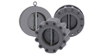
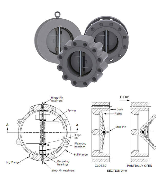
The dual Plate Check Valve is an all purpose non return valve that is much stronger, lighter in weight and smaller in size compared to a conventional swing check valve or life check valve. The Dual Plate Check Valve design is the result of attempts to solve the problems associated with swing check valve and lift check valve. The Dual Plate Check Valve employs two spring-loaded plates hinged on a central hinge pin. When the flow decreases, the plates close by torsion spring action without requiring reverse flow. This design offers the twin advantages of No Water Hammer and Non Slam simultaneously. All features put together make the Dual Plate Check Valve one of the most efficient design. It is also referred as SILENT CHECK VALVE. The valve design conforms to APS 594 as well as API 6D except face to face dimensions of ANSI 125 cast iron valves of sizes 65mm (2½”) to 300mm (12”). Valve inspection and testing conforms to API 598. Dual Plat Check Valves are available in wafer design, flanged wafer design and extended design with flanged ends having face to face dimensions as that of a swing check valve.

image
image
Pressure Seal Bonnet Gate, Globe and Check Valve

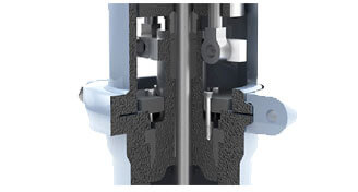
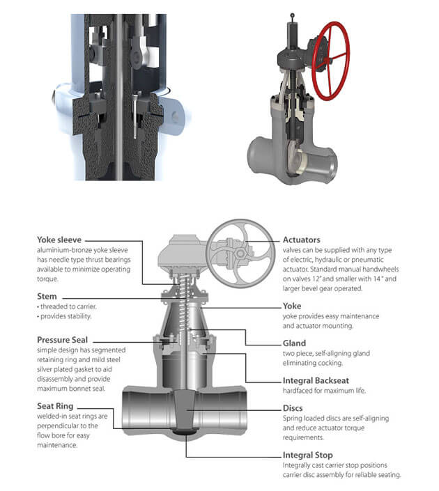
Pressure seal bonnet valves are designed and manufactured to ensure the perfect seal, as well as to allow for easy dismounting and assembly. As line pressure increases, seating forces also increase to assure its performance in high temperature and pressure application The body of the high pressure gate valve is designed as a one piece casting, with smooth inside contour providing maximum flow efficiency. The body has an integral casting guiding system to guide the wedge full through the valve stroke. The pressure seal type gate valve is designed with 4holes in the neck at the region of the segmental retainer for a proper disassembly. The contacting surface the pressure seal gasket outside has a stainless steel 18-8 inlay to assure soundness and corrosion the body is seal welding for body seat rings.

image
image
Bellow-seal Gate Valve and Globe Valves

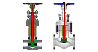
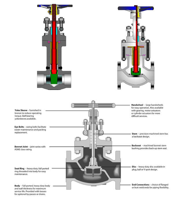
Bellow sealed valves are designed to eliminate valve leakage creating hermetic sealing and manufactured with hydro-formed multi-fly bellows, welded to the stem and bonnet. Conventional gland packing is replaced by a bellow cartridge ensuring emission free use. Wall Thickness and General Designs are API 602 for forged gate valves/ ASME B 16.34/BS 5352 for forged globe valves/ API600 for cast valves. Various test has performed under the max pressure condition. Stem backseat and stem packing ensure the perfect sealing when a bellows is damaged. And Satellite 6 faced both seat and wedge/disc to prevent seizing and galling.

image
image
Knife gate valve

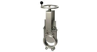
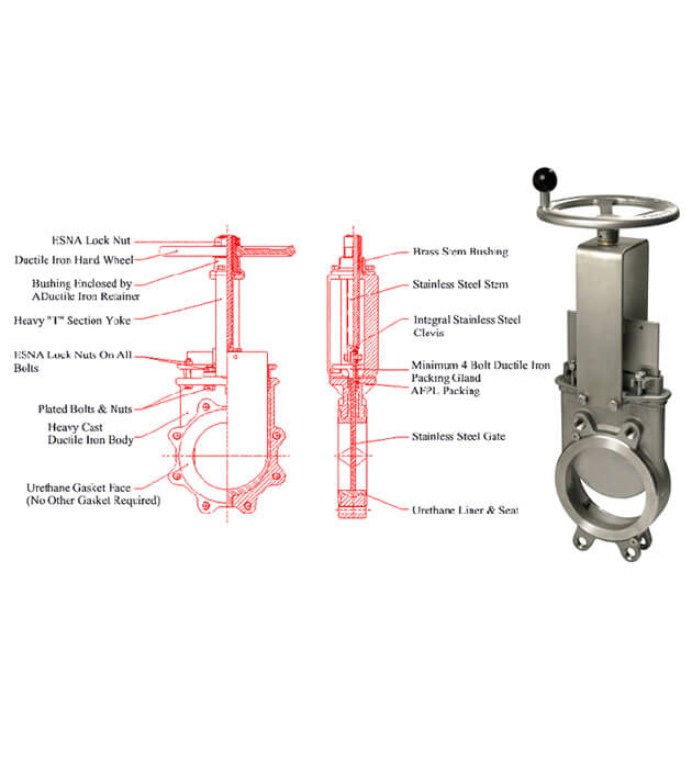
A knife gate valve is a component that utilizes a blade to cut through clogging of heavy liquids. These valves were designed to work in some of the most corrosive, erosive and abrasive environments in the world.

Knife gate valves were originally designed for the pulp and paper industry. Stringy pulp would get stuck between the wedge and the seat of a normal gate valve and prevent flow shut-off. Knife gate valves were specially designed with a sharp edge to cut through the pulp and seal.

because of this highly effective design characteristics, knife gate valves have become invaluable when it comes to applications that involve viscous fluids, slurry and other systems where impingement is an issue.

Knife gate valves are used is a lot of processing plants today and come in large sizes which make it easier to handle thick flows of light grease, heavy oils, varnish, slurry, waste water and paper pulp. It's important to note that these valves do have low-pressure limitations and are designed to seat the blade into an elastomer seal once the blade cuts through the substances its handling. Thick liquids easily glide over these soft seals with no interference, however, when a solid mass or powder passes through the knife gate, the bulky, dry material ends up packing into the soft seals located at the end of the gate. When this happens, the seals eventually won’t close tightly enough. If this happens the seals will need to be replace.

the biggest difference between knife gate valves and gate values is that gate valves are manufactured to ANSI standards while knife gate valves comply with TAPPI standards. The gate valve is also flanged, wider dimensionally, ANSI pressure rated and its API leak tightness standards need to be met. Gate values are bi-directional, and widely used in fluid applications and they only come with metal seats. Another difference between a knife gate valve and an ANSI gate valve is within the packing gland area. A gate valve has a v-ring packing set that seals the shaft that is attached to the gate. Knife gate valves have a packing gland area that seals around the gate.

image

Highlights of the Valves

Materials

Forged carbon Steel valves: ASTM A105/ A105M

Forged carbon Steel valves For low Temprature Service: ASTM A350/ A350M (LF1, LF2, LF3, LF5, LF6, LF9, LF 787)

Forged Alloy Steel and Stainless Steel valves For High Temprature Service: ASTM A182/ A182 M-98ª(F 304, F 304H, F 304L, F 304N, F304 LN, F 309H, F310, F 310H, F 310 MoLN, F 316, F 316H, F 316L, F 316N, F 316LN, F 317, F 317L, F 347, F 347 H, F 348, F 348 H, F 321, F321 H)

Forged Duplex Steel valve : ASTM A182 (F 50, F 51, F 52, F 53M F 54, F 55, F 57, F 59, F 60, F 61, F 904L)

ASTM A352/ A352M (LCA, LCB, LCC, LC1, LC2, LC2-1, LC3,LC4, LC9(J31300), CA6NM)

ASTM A351/ A351 M (CF8(F304), CF3(F304L), CF3M(F316L), CF8M(F316))

ASTM A217/ A217 M-98a( WC1, WC4, WC5, WC6, WC9, WC11, C5, C12, C12A,

ASTM A351/ A351 M (CN7M, CD4MCu, CG8M, CK3MCuN)

SA-494/ SA-494 M(UNS N02100, UNS N24135, UNS N04020, UNS N24030, UNS N24025, UNS N24130, UNS N30012, UNS N30007, UNS N30003, UNS N06040, UNS N30002, UNS N30107, UNS N26455, UNS N26625, UNS N26055, UNS N30003, UNS N26022, UNS N08826, UNS N26059)

Standard

API 6D, API 600, API 599, API 598, API 608, API 602, ASME B16.10, ASME B16.5, ASME B16.47 (Serie A and Serie B) and MSS SP44 are the key specifications covering the dimensions and the manufacturing tolerances of valves.

How can we help you?

If you have questions, comments or feedback, please feel free to contact us. We are ready to help!