Technical Data
• Capacity: up to 900 m3 /min (up to 220,000 Nm3 /h)
• Discharge pressure: up to 450 bar (458.8 kgf/cm2 )
• Drive power: up to 32,000 kW
• Efficiency: up to 85%
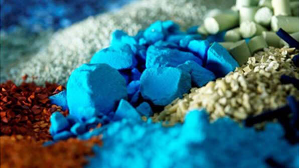
Compressible
Gases Nitrogen, Chlorine, Air, Natural Gas, Associated Petroleum Gas, Fuel Gas, Hydrocarbon Process Gas, Flare Gas, Hydrogen-Bearing Gas, Coke Oven Gas, Other Gases
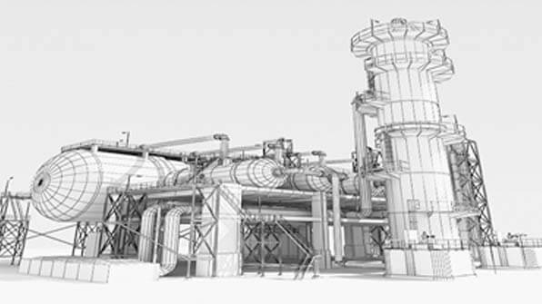
Design Features & Advantages
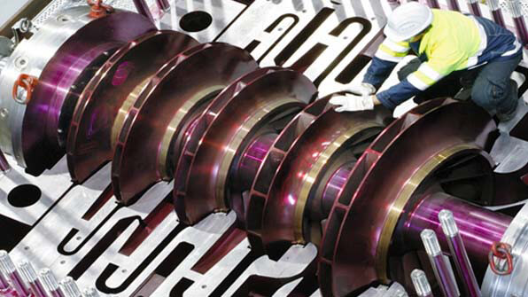
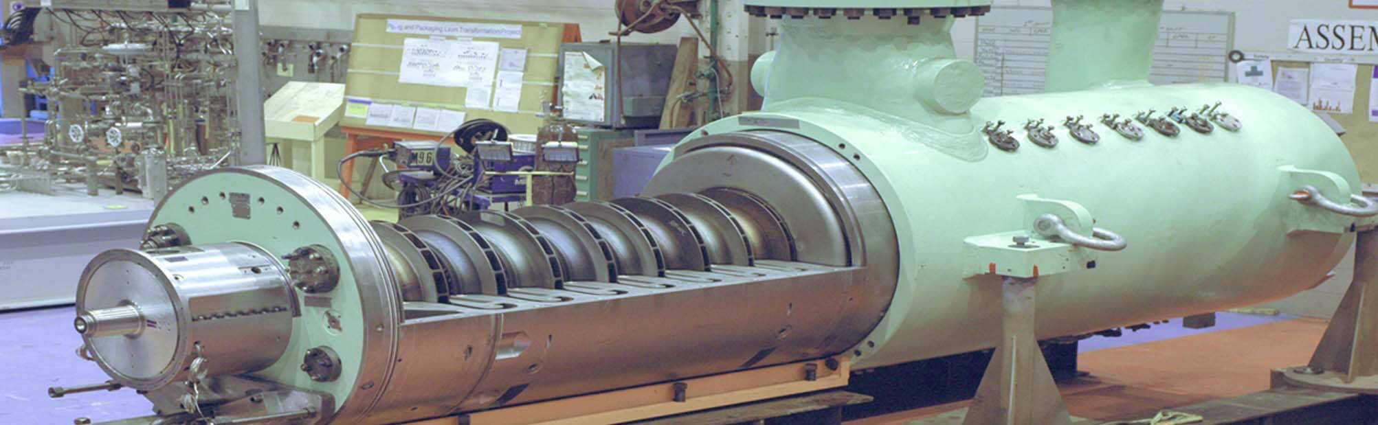
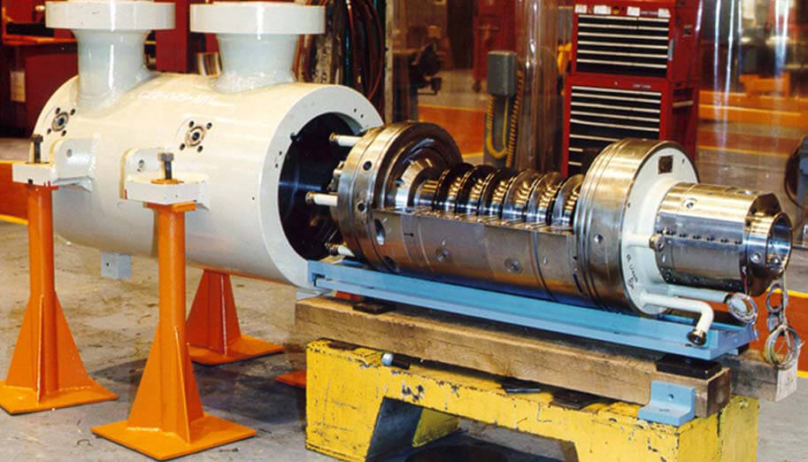
• A vertically split casing allows fabrication of high-pressure compressors for explosive gases
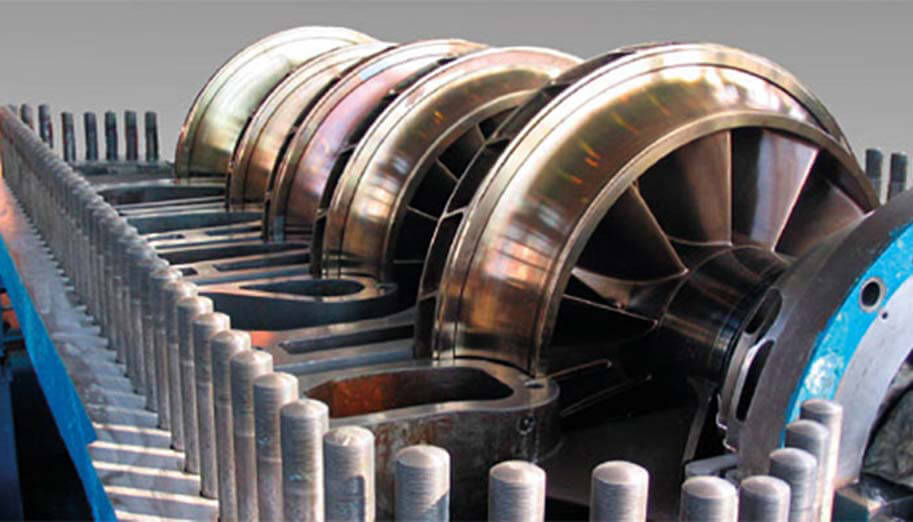
• Flow path with high-performance compression stages
• Special locks securing solid forged caps that cover the ends of the steel cylinder, provide quick and easy maintenance and repair of the compressor
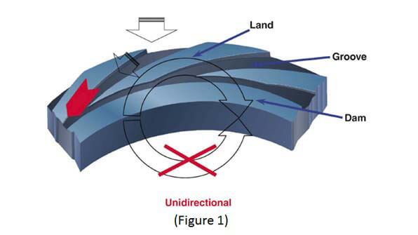
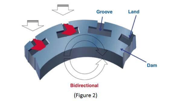
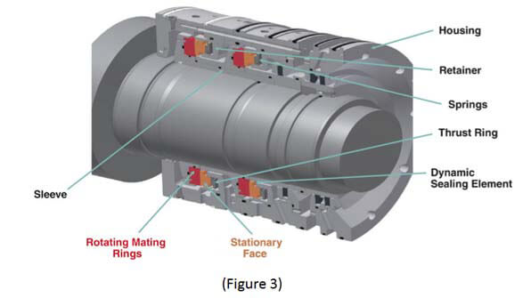
• Dry gas seals to provide complete purity of compressed gas and prevent its leakage into compressor room
• Active magnetic bearings for the rotor suspension
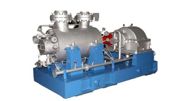
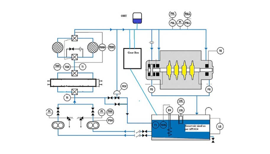
• Intercooling of compressed gas between sections in the two-stage casings
• Automation system based on microprocessor controller
• Many years of operation in real conditions have proven high reliability and efficiency of the construction components